Floor plans include a comprehensive site survey and creation of AutoCAD files for each floor of the building (including any floors below grade), bearing the signature and seal of a registered design professional, marked to reflect exit routes, in-building relocation areas, and other information contained in plan documents amenable to graphic representation.
These final floor plans will depict the following elements:
- A floor plan table of contents, including drawing number and title.
- In-building relocation area table of contents
- Exits
- Evacuation Routes
- Fire Barriers
- Areas of Refuge (if any)
- Stairs with letter designation, as determined by the building signage
- Access and convenience stairways
- Elevator bank letter and car number designations as per building signage
- Fire Command Center (aka: Fire Command Station)
- Fire Warden Phones
- Manual Fire Alarm Boxes (Pull Stations)
- Standpipe Hose Outlets
- Sprinkler and standpipe system control valves
- Any part of the building not protected by sprinkler system
- Emergency power generator and fuel supply, main/day tank
- Show legend for all symbols and abbreviations used
- In-Building Relocation Areas
- Site/Plot Plan
- North arrow shown on all drawings
<< Back to: Commercial Properties Floor Plans / Riser Diagrams
Standpipe and Sprinkler Riser Diagrams include a comprehensive site survey and creation for each individual suppression system located in the building.
These final Standpipe and Sprinkler Riser Diagrams will depict the following elements:
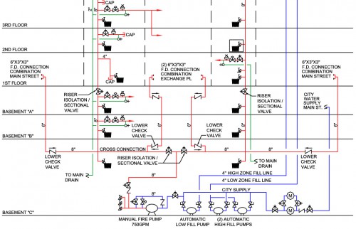
Standpipe Systems
(Including but not limited to)
- City Domestic Water Inlet
- City Fire Water Inlet
- FD Connection(s) (aka: Siamese Connections)
- Fill Pump(s)
- Fire Pump(s) ~ Indicating Output and GPM
- Gravity Tank(s) ~ Indicating Total Capacity and Fire Reserve
- Hose (Type and Length)
- Hose Outlets (per floor)
- Isolation / Sectional Valves
- Lower Check Valve
- Pressure Reducing Valves
- Risers ~ Notating Size and Location
- Roof Manifold(s)
- Site / Plot Plan
- Special Service Pumps
- Upper Check Valve Assembly
Sprinkler Systems
(Including but not limited to)
- Booster Pump(s)
- City Domestic Water Inlet
- City Fire Water Inlet
- Control Valves (Floors)
- Dry Pipe Valves
- FD Connection(s) (aka: Siamese Connections)
- Fill Pump(s)
- Fire Pump(s) ~ Indicating Output and GPM
- Gravity Tank(s) ~ Indicating Total Capacity
- Isolation / Sectional Valves
- Lower Check Valve
- Pre-Action Sprinkler Valves
- Pressure Reducing Valves
- Pressure Tank(s) ~ Indicating Capacity
- Risers ~ Notating Size and Location
- Site / Plot Plan
- Upper Check Valve Assembly
<< Back to: Commercial Properties Floor Plans / Riser Diagrams